

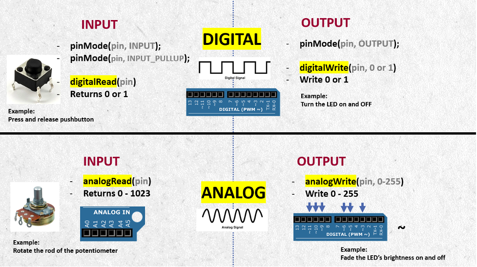
What is the Difference Between Analog and Digital Pins in Arduino?
Many people who are new to Arduino often find it tricky to understand the difference between analog and digital pins in Arduino. They get confused about where and how to connect electronic components and sensors to the board, wondering whether to connect them as outputs or inputs. Choosing the code functions usually makes it a little bit difficult for beginners.
In this article, we’ll simplify all these challenges to make them as straightforward as they should be. We’ll discuss the difference between analog and digital pins in Arduino, as well as the variations between reading from inputs and writing to outputs. We’ll also cover how to implement these concepts in your code. It’s important to note that our focus will be on the Arduino Uno type, bearing in mind that different types of Arduino boards may have varying numbers of digital or analog pins.
What is a Digital Signal?
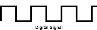
Digital signals, in the realm of electronics, are characterized by discrete, distinct values represented typically as binary code, using combinations of 0s and 1s. Unlike analog signals, which vary continuously, digital signals convey information in a more structured manner. This binary language is the foundation of modern computing, enabling precise storage, processing, and transmission of data. Digital systems are known for their reliability and resistance to noise, making them ideal for long-distance communication. Devices such as computers, smartphones, and digital cameras rely heavily on the efficiency and accuracy of digital signals for their operation.
How to know whether the sensor or the electronic component works on Digital or Analog Signals?
The datasheet for every electronic component from the manufacturer provides information about whether it operates on digital or analog signals. Certain sensors have the capability to function with either digital or analog signals, and the choice between the two depends on how the user intends to utilize the sensor. This also plays a role in understanding the difference between analog and digital pins in Arduino.
What is an Analog Signal?
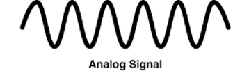
Analog signals, on the other hand, operate in a continuous manner, representing information through a smooth, uninterrupted waveform. These signals can theoretically take an infinite number of values within a given range, offering a nuanced representation of physical quantities like voltage, temperature, or sound waves. Analog technology is often associated with the natural world and is used in applications where a continuous and accurate representation of data is crucial. Analog signals are susceptible to noise and may experience degradation over long distances, but they remain relevant in areas such as audio processing, where the subtleties of continuous signals are essential for faithful reproduction.
How to know whether the sensor or the electronic component works on Digital or Analog Signals?
The datasheet for every electronic component from the manufacturer provides information about whether it operates on digital or analog signals. Certain sensors have the capability to function with either digital or analog signals, and the choice between the two depends on how the user intends to utilize the sensor.
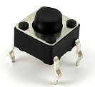
(The Pushbutton is an example of a Digital Component. When you press or release the pushbutton, you are making digital signals. It is only ON or OFF. It is ONE or ZERO. In other words, it is HIGH or LOW.)
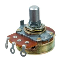
(The Potentiometer is an example of an Analog Component. A potentiometer works as an adjustable variable resistor where you can change the resistor’s value when rotating its rod. This results in making a range of analog values.)
Afterward, the next step involves determining whether the electronic component functions as an output, where it receives a value, or as an input, where it provides readings. This difference between analog and digital pins in Arduino becomes crucial when writing the code and specifying the functions related to these components.
Once you’ve identified whether your electronic component is digital or analog and determined whether it functions as an output or input, the outcome falls into one of four categories: Digital Output, Digital Input, Analog Output, or Analog Input. We will now dive into each category, providing examples and exploring the syntax code associated with them.
Arduino Digital Pins 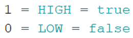
When talking about the digital pins in Arduino Uno, we are talking about the upper side pins numbered from 0 to 13 (14 I/O digital pins).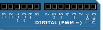
Note: The Arduino Uno utilizes Pins 0 and 1 for serial communication with the computer through the USB cable. Attaching devices to these pins may result in interference, affecting both serial communication and any other intended functions, such as uploading sketches to the Arduino board.
Note: The pinMode (pin, mode) function is used to configure the specified pin to behave either as an input or an output. These 14 pins can be used as digital input or as digital output. Therefore, it is a must to use the pinMode() function in the setup() scope when starting to write the code.
This function takes two parameters:
Pin: Arduino pin number to set the mode for
Mode: OUTPUT, INPUT, or INPUT_PULLUP
Example:
void setup() {

  pinMode(11, OUTPUT);          // sets the digital pin 11 as output

  pinMode(12, INPUT);           // sets the digital pin 12 as input

  pinMode(13, INPUT_PULLUP);   // sets the digital pin 13 as input pullup (internal resistor)

}
Let us now talk about digital output and digital input separately!
A) Digital Output:
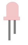
Example: Turning an LED on and off.
We use the function digitalWrite (pin, value) when writing a high or a low value to a digital pin. The pin should be configured as an output with pinMode().
This function takes two parameters:
-
Pin: Arduino pin number
-
Value: High (true,1) or low (false,0)
Code Example:
void setup() {

  pinMode(13, OUTPUT);    // sets the digital pin 13 as output

}

void loop() {

  digitalWrite(13, HIGH); // sets the digital pin 13 on

  delay(1000);            // waits for a second

  digitalWrite(13, LOW);  // sets t0he digital pin 13 off

  delay(1000);            // waits for a second

}
B) Digital Input:
Example: Pressing and releasing the pushbutton.
We use the function digitalRead (pin) when reading the value from a specified digital pin, either high or low. The pin should be configured as an input with pinMode().
This function takes one parameter:
Pin: Arduino pin number
This function returns: high or low
Code Example:
int pbPin = 8;    // pushbutton connected to digital pin 7

int val = 0;      // variable to store the read value

void setup() {

  Serial.begin(9600);      // Setup Serial

  pinMode(pbPin, INPUT);    // sets the digital pin 7 as input

}

void loop() {

  val = digitalRead(pbPin);   // read the input pin

  Serial.println(val);      //print values on the Serial Monitor

}
Note: INPUT_PULLUP could be used with pushbuttons and other electronics components to activate the internal resistor inside the Arduino instead of putting an external resistor in hardware.
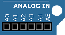
Arduino Analog Pins
Note: Analog pins can be used as digital pins, but not vice versa.
Note: The pinMode (pin, mode) function is optional when using the analog pins in Arduino, so you might not write it when using the analog functions.
Let us now talk about Analog Output and Analog Input separately!
A) Analog Output (Pulse Width Modulation):
Example: Fade your LED’s brightness on and off.
We use the function analogWrite (pin, value) when writing a value between 0 to 255 on any of the Pulse Width Modulation pins (PWM). The resolution of the PWM function has a resolution of 8 bits, which gives us 255 analog output levels. Arduino Uno has 6 PWM pins, which are marked with the wave sign.
This function takes two parameters:
Pin: Arduino pin number to write on
Value: The duty cycle between 0 (off) and 255 (on)
Code Example:
int analogPin = 3;   // potentiometer connected to analog pin 3

int val = 0;         // variable to store the read value

void setup() {

    Serial.begin(9600);  // Setup Serial

}

void loop() {

  val = analogRead(analogPin);  // read the input pin

  Serial.println(val);  // print the values on the Serial monitor

}
B) Analog Input:
Example: Fade your LED’s brightness on and off.
int ledPin = 9;      // LED connected to digital pin 9

void setup() {

}

void loop() {

  for(int val=0;val++;val<=255)

    analogWrite(ledPin, val); //analogWrite values from 0 to 255

}
We use the function analogRead (pin) when reading the values of a specific pin. Arduino boards are equipped with a versatile 10-bit analog-to-digital converter that can handle multiple channels. In practical terms, this converter translates input voltages ranging from 0 to the operational voltage (either 5V or 3.3V) into integer numbers within the range of 0 to 1023.
Arduino Uno has 6 analog input pins; the pins are numbered starting with the letter ‘A’, which refers to Analog.
This function takes two parameters:
Pin: Arduino pin number.
This function returns: A value between the range 0 – 1023
int analogPin = 3;   // potentiometer connected to analog pin 3

int val = 0;         // variable to store the read value

void setup() {

    Serial.begin(9600);  // Activate the Serial Monitor

}

void loop() {

  val = analogRead(analogPin);  // read the input pin

  Serial.println(val);  // print the values on the Serial monitor

}
Understanding the difference between analog and digital pins in Arduino helps beginners make better choices about pin usage, sensor compatibility, and code functions, leading to smoother project implementation and fewer hardware errors.