Description :
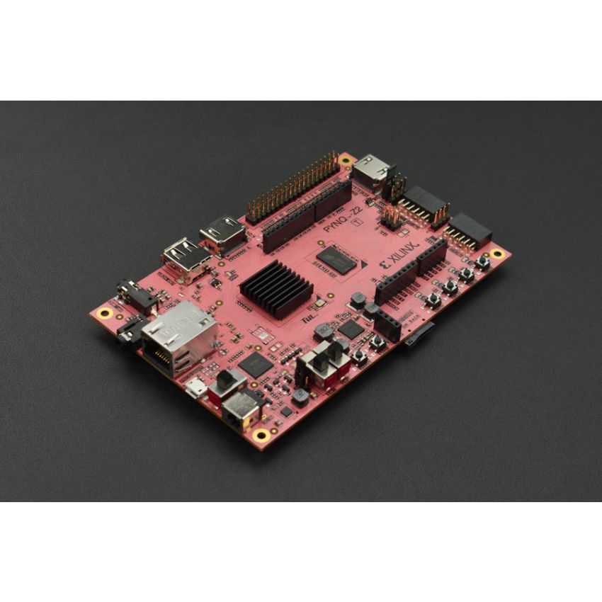
- PYNQ-Z2 is an FPGA development board based on the Xilinx XC7Z020 FPGA, specifically designed to support PYNQ, an open-source framework for embedded programmers.
- PYNQ allows embedded programmers to explore the capabilities of Xilinx ZYNQ SoCs without having to design programming logic circuits.
- The board includes Ethernet, HDMI Input/Output, MIC Input, Audio Output, Arduino interface, Raspberry - Pi interface, 2 Pmod, user LED, push-button, and switch.
- PYNQ utilizes the benefits of programmable logic and microprocessors in Zynq to build more powerful and versatile embedded systems.
- PYNQ can be used for a wide range of applications including parallel hardware execution, high frame-rate video processing, hardware-accelerated algorithms, real-time signal processing, high-bandwidth IO, and low latency control.
- The board can be extended with Pmod, Arduino, and other peripherals, as well as general-purpose GPIO pins.
- PYNQ is widely used for machine learning research and prototyping.
- When used with the DF Arduino or Raspberry Pi expansion shield, the possibilities are endless.
- Specifications:
•Outline Dimension: 87mm*138mm/3.43”*5.43"
•ZYNQ XC7Z020-1CLG400C Board:
•650MHz dual-core Cortex-A9 processor
•DDR3 memory controller with 8 DMA channels and 4 High-Performance AXI3 Slave ports
•High-bandwidth peripheral controllers: 1G Ethernet, USB 2.0, SDIO
•Low-bandwidth peripheral controller: SPI, UART, CAN, I2C
•Programmable from JTAG, Quad-SPI flash, and MicroSD card
•Programmable logic equivalent to Artix-7 FPGA
•13,300 logic slices, each with four 6-input LUTs and 8 flip-flops
•630 KB of fast block RAM
•4 clock management tiles, each with a phase-locked loop (PLL) and mixed-mode clock manager (MMCM)
•220 DSP slices
•On-chip analog-to-digital converter (XADC)
•Memory:
1.512MB DDR3 with 16-bit bus @ 1050Mbps
2.16MB Quad-SPI Flash with factory programmed 48-bit globally unique EUI-48/64™ compatible identifier
3.MicroSD slot
•Power:
1.Powered from USB or 7V-15V external power source
•USB and Ethernet:
1.Gigabit Ethernet PHY
2.Micro USB-JTAG Programming circuitry
3.Micro USB-UART bridge
4.USB OTG PHY (supports host only)
•Audio and Video:
1.HDMI sink port (input)
2.HDMI source port (output)
3.I2S interface with 24 bit DAC with 3.5mm TRRS jack
4.Line-in with 3.5mm jack
•Switches, Push-buttons, and LEDs:
1. 4 push-buttons
2. 2 slide switches
3. 4 LEDs
4. 2 RGB LEDs
•Expansion Connectors:
1. Two standard Pmod ports
2. 16 Total FPGA I/O (8 shared pins with Raspberry Pi connector)
3. Arduino Shield connector
4. 24 Total FPGA I/O
5. 6 Single-ended 0-3.3V Analog inputs to XADC
6. Raspberry Pi connector
7. 28 Total FPGA I/O (8 shared pins with Pmod A port)